Today's medical portable devices facilitate patient care, free movement, and even use the device while on the go. In order to realize the "portable" function of portable electronic medical equipment, it must have the characteristics of miniaturization and low power consumption. In addition, these devices require extreme precision to ensure patient safety. Medical devices use a variety of different sensors to monitor the health of the patient, and then the sensor converts the physiological signals into electrical signals for analysis by the electronic device. Signal path design is particularly important for portable medical devices because the signals transmitted in medical devices are relatively weak and subject to interference from many sources of noise. This article will discuss how to connect sensors to matched PowerWise amplifiers for both ECG and blood glucose meter applications to extend battery life and improve diagnostic safety.
Operating principle of electrocardiograph
The electrocardiograph (ECG) records the patient's heartbeat activity in real time. The heartbeat signal is measured by three electrodes connected to the patient's body. Figure 1 shows the ECG signal output from one of the electrodes. The figure contains five measurement points, Q, P, R, S, and T. These measurement points can be used to diagnose the possibility of a patient suffering from heart disease.
This article refers to the address: http://
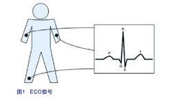 |
The signal collected from the electrodes is in the range of 400 μV up to 5 mV with a 3 dB corner frequency at 0.05 Hz and 100 Hz. Such signals are generally subject to a lot of interference, such as electrode contact noise, power line noise (50MHz), breathing, muscle activity, and interference from other electronic devices.
ECG signal adjustment
As stated above, the ECG's signal path must be able to modulate noise from different sources. To combat DC noise, a high-pass filter can be used. However, the most troublesome is the 50 Hz noise because it is just in the same range as the signal we collected. To eliminate this common mode noise, a measurement instrumentation amplifier needs to be built. This configuration is ideal because it amplifies the useful differential signal while rejecting the common-mode voltage, which helps to separate the weakly valid signal from the background noise. As shown in Figure 2, this instrumentation amplifier is implemented with the LMP2234 (four-channel, micropower, high-precision RRO operational amplifier) ​​and high-precision resistors (0.1%).
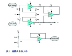 |
A1, A2, A3, A4: LMP2234
R1, R2: 2 MΩ
R3, R5: 40 kΩ
R4: 20 kΩ
R6, R7: 10 kΩ
R8, R9: 10 kΩ
R10, R11: 20 Kω
LMP2234 is fabricated using the VIP50 process technology, an insulated silicon BiCMOS process. Ultra-low power amplifiers fabricated in this process are ideal for battery-powered, low-power applications. The process has an operating voltage range of 1.8 to 5.5V and a quiescent current of 36μA, which helps extend the life of the battery in portable systems. The LMP2234 is a member of the LMP family of precision amplifiers, and its high-impedance CMOS input makes it an ideal choice for measurement instruments and other sensor interface applications.
Since the amplitude of the signal from the electrode is extremely low, the DC parameters of the amplifier are important. The LMP2234 has a maximum offset voltage of 150V (typically 10 V), while the offset voltage drift temperature coefficient and bias current are only 0.3 μV/°C and ±20 fA, respectively. These high-precision, tight specifications allow the LMP2334 to perform exceptionally well in maintaining system accuracy and long-term stability.
This measurement instrumentation amplifier contains two stages. The last stage (ie, the output stage) is a differential amplifier that rejects the DC level and both the interference and noise voltage sources that affect both inputs. The first stage (ie, the input stage) consisting of two amplifiers is configured as a buffer that isolates the input. However, based on the mismatch between the amplifiers, they cannot be connected to each other, so a balancing resistor is added between the two amplifiers. Multiplying the gains of the two stages yields the gain of the measuring instrumentation amplifier. In theory, the common mode rejection ratio (CMPR) should be infinite, but due to the resistor mismatch, the non-zero common mode gain of the output stage is very small. In the input stage of the circuit, the current flowing through all the resistors is the same. This depends on the LMP2234's high input impedance and low input bias current.
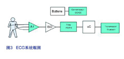
The output voltage is defined as: 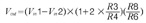
The maximum amplitude of the input signal is only 5mV, but in order to establish the gain, we must consider the DC offset voltage of the electrode, which can sometimes be as high as ±300mV. The rail-to-rail output of the LMP2234 swings from the supply rail to 15mV, increasing the dynamic range of the system. In addition, a bias voltage divider consisting of R10 and R11 provides a voltage that is exactly half the supply voltage required for the patient's sign in the correct patient segment.
As shown in Figure 3, a high-pass filter is used to suppress DC devices that can cause saturation of the next gain stage. The high pass filter has a cutoff frequency of 0.5 Hz. The filter is implemented using a second-order Sallen Key type Butterworth topology. The second stage is a low-pass filter with a 100 Hz cutoff frequency and a gain of 100, and is also implemented in a Sallen Key topology. The analog filters of the Sallen Key class are built around an operational amplifier with resistors and capacitors. The inductor was not used because it was too bulky, bulky and not perfect.
 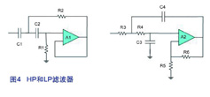 |
| C1: 1 μF | R3: 5.36 kΩ |
| C2: 220 nF | R4: 14.3 kΩ |
| R1: 1.24 MΩ | C3: 33 nF |
| R2: 365 kΩ | C4: 1 μF |
| R5: 10 kΩ | |
| R6: 1 MΩ |
Both filters are implemented using the low-power op amp LMV552, which is fabricated using National's VIP50 process. With a bandwidth of 3MHz, each amplifier consumes only 34μA of current, and the bandwidth/power ratio is the highest in its class of op amps. The LMV552 has a rail-to-rail output stage and an input common-mode range that extends below ground. The operating supply voltage range is 2.7V to 5.5V.
A battery operated system requires a DC/DC boost to provide the 3.3V required for the signal path. The LM2623 is a high efficiency, general purpose step-up DC-DC switching regulator designed for use in battery-powered low input voltage systems. The regulator accepts input voltages from 8V to 14V and converts them to a stable output voltage of 1.24V to 14V. With the LM2623, the system can be as efficient as 90%.
If the system requires patient safety isolation, it can be achieved by using galvanic isolation, optocoupler capacitance, and magnetic coupling. Although this article focuses on the front end of ECG, when developing medical electronic systems, the issue of safety standards cannot be ignored.
Bluetooth transmission
Heartbeat recordings can be wirelessly transmitted to a computer, mobile phone or PDA. Bluetooth technology is stable, reliable, easy to use, cost-effective, and has a wide range of coverage, making it a popular wireless technology for patient monitoring.
National's LMX9838 Bluetooth Serial Port Module is a highly integrated device that includes a Bluetooth 2.0 baseband controller, 2.4GHz radio, crystal, antenna, LDO, and discrete components. The Bluetooth node is fully functional and compact (10 mm x 17 mm x 2.0 mm).
Hardware and software are included in this complete solution for applications with complete high and low Bluetooth stacking layers, Universal Access Gauge (GAP), Service Discovery Application Specification (SDAP) and Serial Port Specification (SPP). The module contains a configurable service database to cater to additional service specification requirements on the master. In addition, the LMX9838 is certified for Bluetooth end product and can be used directly in the final application without any testing or payment technology license fees.
Based on National's CompactRISC 16-bit processor architecture and digital smart radio technology, the LMX9838 is an optimized solution that fully satisfies the data processing and link management requirements required for Bluetooth nodes.
Another example: blood glucose meter
The blood glucose meter is an important device for patients with diabetes. Blood sugar control can undoubtedly help reduce the risk of patients and improve the quality of life of patients. There are usually two methods for measuring blood glucose: reflective photometry and electrochemistry. In an optical method, blood sugar reacts with another compound on the test strip to produce a color mark whose depth is proportional to the blood sugar concentration. The principle of reflective photometry is to quantify the depth of the color by measuring the reflected light from the LED: the higher the blood glucose concentration, the weaker the reflected light. The LED captures the light and converts it into an electrical signal.
However, most blood glucose meters use an electrochemical method based on oxidation. In this method, the blood glucose sensor is a test strip containing an enzyme and three electrodes. Two of the electrodes are used for measurement and the other for reference. When a blood sample is placed on the test strip, electrons are delivered to the electrode. Electrochemistry quantifies the number of electrons: the amount of electrons produced is proportional to the concentration of blood sugar. When a reference voltage (typically 200mV) is applied to the test strip, the electrons are converted into a current proportional to the blood glucose concentration. This method is called current analysis. However, the resulting current is quite weak, typically ranging from μA to nA, and needs to be converted to a voltage that can be processed.
 |
Figure 5 shows a block diagram of a complete solution that is battery powered and can use the LM2623 to provide a 3.3V supply voltage. The current measured by the electrode is then converted to a voltage via an operational amplifier, which is then sent to the microcontroller for processing and finally displayed on the LCD screen.
R1= 47 kΩ and R2= 3 kΩ, Rf= 25 kΩ
Let's dive into the current-to-voltage conversion achieved by a transimpedance amplifier. The gain of this topology is measured as the ratio of the output voltage to the input current, meaning that the feedback resistor Rf must be large enough to detect a small current. However, the capacitance of the amplifier input (Cin) plus the feedback resistor (Rf) produces a phase lag that causes the gain peak to appear and affects the stability of the circuit. Capacitor Cf is a stability margin used to generate a pole and increase the phase angle. In addition, this capacitor can also be used to limit the bandwidth to achieve noise suppression. As mentioned earlier, the current output from the sensor is very weak, which means the amplifier must have extremely high precision specifications. First, the current noise of the amplifier used must be low, so the LMP2232 with 10 fA/sqrt (Hz) is the best choice.
Another parameter to note is the bias current of the amplifier, especially when the feedback resistor is large. In addition, the effect of the offset voltage is equally important, and the error from these two parameters can be calculated as Verror = Vos + Ib x Rf. The LM2232's offset voltage and bias current are 230μV (typically 10μV) and 50pA (typically 20fA) over the operating temperature range. Therefore, the LM2232 is the best choice for this type of application.
As noted above, this amplifier is a micropower component and the dual channel model consumes only 13μA.
in conclusion
Whether it is an electrocardiogram or a blood glucose measurement application, the most important thing for portable medical devices is to ensure patient safety and mobility. Ultra low power and ultra high precision are uncompromising requirements when designing the system. The above two examples show that National Semiconductor products have advantages in terms of accuracy, power consumption, size and flexibility.
IPA Presaturated Cleaning Wipes are made from 55% cellulose and 45% polyester, presaturated with 99.9% IPA solution. The size is 127 x 152mm, any customized size is also available. IPA Cleaning Wiper is a general use product suitable for most applications such as printhead, platen rollers, screen, case surface,etc. During using a Presaturated Cleaning Wiper, please make sure you have turned off device power in case of electric shock.

IPA Cleaning Wipes
IPA Cleaning Wipes,Alcohol Cleaning Pads,Techspray IPA Cleaning Wipes,Presaturated Cleaning Wiper,Wet Cleaning Tissues,Pre Moistened Cleaning Tissues
Mediclean Technology Co.,LTD. , http://www.mediclean-tech.com