1. Introduction In the conventional system of variable frequency speed regulation composed of general-purpose inverter, asynchronous motor and mechanical load, when the position of the motor can be driven down, the motor may be in the regenerative braking state; or when the motor is from high speed to When the speed is reduced at low speed (including parking), the frequency can be abruptly reduced. However, due to the mechanical inertia of the motor, the motor may also be in the regenerative state. The mechanical energy stored in the transmission system is converted into electric energy by the motor and passed through the six freewheeling of the inverter. The diode is sent back to the DC link of the frequency converter. The inverter at this time is in a rectified state. At this time, if no energy consumption measures are taken in the inverter, this part of the energy will cause the voltage of the energy storage capacitor of the intermediate circuit to rise. If the brake is too fast or the mechanical load is a hoist, this part of the energy may damage the inverter, so we should seriously consider this part of the energy.
In general-purpose inverters, there are two most common treatment methods for regenerative energy: 1. Dissipated into the "brake resistor" that is artificially connected in parallel with the capacitor in the DC loop, called the dynamic braking state; Returning it to the grid is called a feedback braking state (also known as regenerative braking state). There is also a braking method, namely DC braking, which is used for situations requiring accurate parking or irregular rotation of the brake motor due to external factors before starting.
There are many experts in books and publications who have talked about the design and application of inverter braking, especially in recent times there have been many articles about "energy feedback braking". Today, the electrical automation technology network organizes a new type of braking method. It has the advantages of four-quadrant operation of "feedback braking" and high operating efficiency. It also has the advantages of "power braking" without pollution to the power grid and high reliability.
2. Dynamic braking:
The method of absorbing the regenerative electric energy of the motor by the braking resistor provided in the DC link is called dynamic braking. (Figure 2.1). 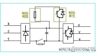
Figure 2.1 The principle of dynamic braking has the advantages of simple structure; no pollution to the power grid (compared with the feedback mechanism), low cost; the disadvantage is low operating efficiency, especially when it is frequently braked, it will consume a lot of energy and braking resistor The capacity will increase.
Generally, in the general-purpose inverter, the small-power inverter (below 22KW) has a built-in brake unit, and only needs to add a brake resistor. High-power inverters (above 22KW) require external brake units and brake resistors.
3. Feedback brake:
To achieve energy feedback braking, voltage equal-frequency in-phase control, feedback current control and other conditions are required. It uses active inverter technology to invert the regenerative electric energy into an AC returning grid that is in phase with the same frequency of the grid, thus achieving braking (Figure 3.1). 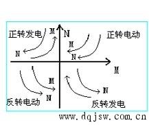
Figure 3.1 Four-quadrant operation diagram The advantage of feedback braking is that it can operate in four quadrants (as shown in Figure 3.2). Power feedback improves the efficiency of the system. The disadvantages are as follows: 1. This feedback braking method can only be used under the stable grid voltage (the grid voltage fluctuation is not more than 10%) which is not easy to malfunction. Because the grid voltage fault time is greater than 2ms during the generator braking operation, commutation failure may occur and the device may be damaged. 2. In the feedback, there is harmonic pollution to the power grid. 3. The control is complicated and the cost is high.
4, the new brake method (the author claims: "capacitor feedback brake")
4.1 Reversible Chopper: 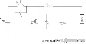
Figure 4.1 The circuit configuration of the reversible chopper reversible chopper is shown in Figure 4.1. The energy flow of such a chopper can be in two directions, which has the characteristic of feeding the energy generated by the load to the power source. When energy is supplied from the power supply E to the load, the device Q2 is turned off, and the device Q1 and the diode D2 function as a step-down chopper; and when the energy is fed from the load side, the device Q1 is turned off, by the device Q2 and the diode D1. It acts as a boost chopper. The role of the reversible chopper in energy feedback is detailed below. 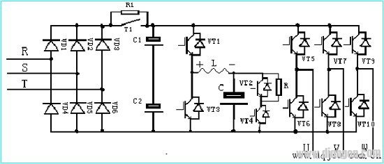
Figure 4.2 Schematic diagram of the capacitive feedback brake main circuit
4.2 main circuit schematic diagram (Figure 4.2)
4.3 System Description:
The rectification part is rectified by a common uncontrollable rectifier bridge (composed of VD1-VD6 in the figure), the filter circuit uses a common electrolytic capacitor (C1, C2 in the figure), and the delay loop adopts a contactor or a thyristor. (T1 in the picture). The charging and feedback loop adopts the principle of reversible chopper. The power module IGBT (VT1, VT2 in the figure), the charging, the feedback reactor L and the large electrolytic capacitor C (the capacity is the Farad stage, which can be determined according to the operating system of the inverter. )composition. The inverter part is composed of power module IGBT (as shown in VT5-VT10). The protection circuit of the large electrolytic capacitor is completed by the chip, the IGBT, and the power resistor.
4.4 Principle analysis:
4.4.1 Motor power generation operation status: The CPU monitors the input AC voltage and DC link voltage in real time, and determines whether to send a charging signal to VT1. Once the DC reference voltage value (such as 380VAC-530VDC) corresponding to the input AC voltage is high, When the value is constant, the CPU turns off VT3, and the charging process of the electrolytic capacitor C is realized by the pulse conduction of VT1. At this time, the reactor L and the electrolytic capacitor C are divided, thereby ensuring that the electrolytic capacitor C operates within a safe range. When the voltage on the electrolytic capacitor C reaches a dangerous value (for example, 370V), and the system is still in the power generation state, and the electric energy is continuously sent back to the DC loop through the inverter part, the safety circuit functions to realize the energy consumption braking (resistance system) Move), control the turn-off and turn-on of VT3, so that the resistor R consumes excess energy, which is generally not the case.
4.4.2 Motor electric running state: When the CPU finds that the system is no longer charging, it will pulse-on the VT3, so that the reactor L will become an instantaneous left-right and negative voltage (as shown in the figure), plus The voltage on the electrolytic capacitor C enables the energy feedback process from the capacitor to the DC loop. By detecting the voltage on the electrolytic capacitor C and the voltage of the DC link, the CPU controls the switching frequency and duty ratio of the VT3 to control the feedback current to ensure that the DC link voltage does not appear too high.
5 system difficulties:
5.1 Selection of reactor:
(a), considering the particularity of the working conditions, assuming that the system has some kind of fault, the position energy load carried by the motor is free to accelerate and fall. At this time, the motor is in a power generation operation, and the regenerative energy is sent back through six freewheeling diodes. To the DC loop, causing the rise, the inverter is quickly charged, and the current will be large. Therefore, the diameter of the selected reactor should be large enough to pass the current at this time.
(b) In the feedback loop, in order to release the electrolytic capacitor as much energy as possible before the next charge, it is not possible to select an ordinary iron core (silicon steel sheet), and it is preferably made of ferrite material. Iron core.
5.2 Difficulties in control:
(a) In the DC circuit of the inverter, the voltage is generally higher than 500VDC, and the withstand voltage of the electrolytic capacitor C is only 400VDC. It can be seen that the control of this charging process is not like the control method of energy braking (resistance braking). . The instantaneous voltage drop generated on the reactor is, the instantaneous charging voltage of the electrolytic capacitor C is, in order to ensure that the electrolytic capacitor operates within a safe range (≤400V), it is effective to control the voltage drop on the reactor, and the voltage The drop is again dependent on the instantaneous rate of change of inductance and current.
(b) In the feedback process, it is necessary to prevent the electric current discharged from the electrolytic capacitor C from passing through the reactor to cause the DC link voltage to be too high, so that the system has overvoltage protection.
6, the main application and application examples:
It is precisely because of the superiority of this new type of braking method (capacitor feedback braking) of the frequency converter. Recently, many users have proposed to equip such a system in combination with the characteristics of their equipment. At present, Shandong Fengguang Electronics Co., Ltd. has switched from the inverter with the feedback braking method (there are still two in normal operation) to the new series of mine hoisting machines with capacitive feedback braking. So far, this kind The inverter with capacitive feedback braking is running normally in the Ningyang Security Coal Mine in Shandong and Taiyuan in Shanxi, filling the gap in China.
With the widening of the application field of frequency converters, this application technology will have great development prospects. Specifically, it is mainly used in mine cages (carrying or loading), inclined well mine cars (single or double cylinders), Lifting machinery and other industries. In all cases, where an energy feedback device is required, it can be used.
We have experience and skill to support customers to tooling for their required waterproof connectors, like IP68 series,micro fit connectors. Etop wire assemblies for various industries have been highly recognized by all the customers and widely used for automobiles, electrical and mechanical, medical industry and electrical equipemnts, etc. Products like, wire harness for car audio, power seat, rear-view mirror, POS ATM, Diesel valve Cover gasket fit, elevator, game machine, medical equipment, computer, etc.
JST Connector,Molex Connector, Multi-Contact Connector, Micro Fit Connectors
ETOP WIREHARNESS LIMITED , https://www.wireharness-assembling.com