Design voltage
The design of cables and accessories must meet the requirements of rated voltage, lightning impulse voltage, operating impulse voltage and maximum system voltage. Its definition is as follows:
Rated voltage
The rated voltage is the reference voltage for cable and accessory design and electrical test, expressed as U0/U.
U0 - the nominal rms voltage between the conductor and insulation shield of the cable and accessory design, in kV;
U - Rated power frequency between phases of conductors designed for cables and accessories
Pressure RMS, in kV.
Lightning impulse voltage
UP - The peak value of the lightning impulse voltage that the cable and accessory design is required to withstand, both the basic insulation level BIL in kV.
Operating surge voltage
US - The peak value of the operating surge voltage that the cable and accessory design is required to withstand, in kV.
System maximum voltage
Um - is the maximum value of the phase-to-phase voltage at any point on the power grid at any time under normal operating conditions. It does not include temporary changes in voltage due to fault conditions and abrupt cuts of large loads, in kV.
Rated voltage parameters are shown in the table below (click to enlarge)

The peak value of the 330kV operation surge voltage is 950kV; the peak value of the 500kV operation surge voltage is 1175kV.
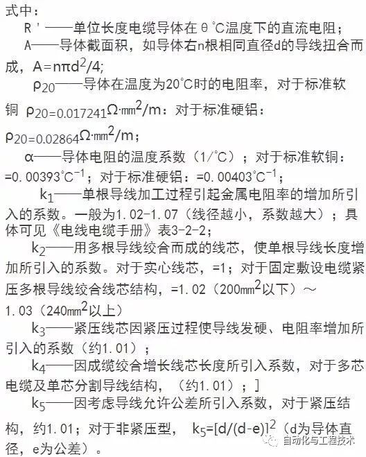
2. Conductor resistance
2.1 Conductor DC resistance
The DC resistance of a unit length cable is calculated using the following formula:

The 20°C conductor DC resistance is detailed in the table below (click to enlarge):
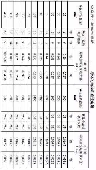
The above is excerpted from "10(6)kV ~ 500kV Cable Technical Standard" (Q∕GDW 371-2009).
2.2 Conductor AC Resistance
Under AC voltage, the core resistance will increase due to skin effect and proximity effect. In this case, the resistance is called effective resistance or AC resistance.
The effective resistance of the cable core is generally adopted by the domestic IEC-287 recommended formula:
R=R'(1+YS+YP)
In the formula:
R——AC effective resistance at the maximum working temperature, Ω/m;
R' - DC resistance at maximum operating temperature, Ω/m;
YS - skin effect coefficient, YS=XS4/(192+0.8XS4),
XS4=(8πf/R′×10-7kS)2;
YP - proximity effect coefficient, YP=XP4/(192+0.8XP4)(Dc/S)2{0.312(Dc/S)2+1.18/[XP4/(192+0.8XP4)+0.27]}, XP4= (8πf/R′×10-7kP)2.
XS4 - Effect of frequency and conductor structure in skin effect;
XP4 - Effect of alternating magnetic fields generated by conductors in the proximity effect;
f - frequency;
Dc——core diameter, m;
S——the distance between the center axis of the core, m;
Ks——core structure constant, split conductor ks=0.435, other conductors ks=1.0;
Kp——core structure coefficient, split conductor kp=0.37, other conductor kp=
0.8~1.0;
For armored or sheathed cables made of magnetic materials, Yp and Ys should be 70% larger than the calculated value, ie:
R=R'[1+1.17(YS+YP)]
3. Inductance of the cable
3.1 Self-induction
The unit length core self-inductance:
Li=2W/(I2L)=μ0/(8π)=0.5×10-7
In the formula:
Li - unit length self-inductance, H/m;
Μ0—vacuum permeability, μ0=4π×10-7, H/m;
The above is generally a solid round conductor, multiple single-wire regular twisted conductors are as follows:
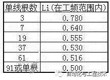
Because the error is not large, the calculation generally takes Li=0.5×10⁻⁷H/m.
3.2 High-voltage and single-core laying cable inductance
For high-voltage cables, generally single-core cables, if laid in the same plane (A, B, C three-phase arrangement from left to right, B phase center, the center distance of the core is S), the inductance formed by the three-phase circuit is based on The electromagnetic theory is calculated as follows:
For intermediate B phase:
LB=Li+2ln(2S/Dc)×10-7 (H/m)
For phase A:
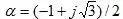
LA=Li+2ln(2S/Dc)×10-7 -α(2ln2)×10-7 (H/m)
For phase C:
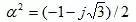
LC=Li+2ln(2S/Dc)×10-7 -α2(2ln2)×10-7 (H/m)
In the formula:


In the actual calculation, the following formula can be approximated:
LA=LB=LC=Li+2ln(2S/Dc)×10-7 (H/m)
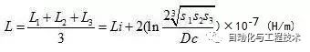
At the same time, the average value of the three-phase cable inductance can be used after cross-positioning, that is:
L=Li+2ln(2×(S1S2S3)1/3/Dc)×10-7 (H/m)
=Li+2ln(2×21/3S/Dc) ×10-7 (H/m)
For multiple cables laid side by side, if the distance between two cables is greater than the distance between phases, the mutual influence of the two cables can be ignored.
3.3 Three-phase cable inductance
The main calculation of three-phase low voltage three-phase cable is arranged as "product" shaped cable. According to the electromagnetic field theory, the operating inductance of the three-core cable is:
L=Li+2ln(2S/Dc) × 10-7
In the formula:
L - inductance per unit length, H/m;
S - distance between cable centers, m;
If the distance between the centers of the three-core cable cable is not equidistant, or the inductance of the three-phase loop cable when the single-core and three-product cable are arranged is calculated as follows:
In the formula:
S1, S2, S3 - The distance between the centers of the cable phases, m.
4. Inductance of cable metal sheath
4.1 Triangle arrangement
The three-phase balanced load AC circuit with three single-core cables laid out in an equilateral triangle is sheathed open, and the inductance of the metal sheath per unit length of cable is:
Ls=2ln(S/rs) × 10-7 (H/m)
In the formula:
Rs - the average radius of the metal jacket of the cable, m.
4.2 Isometric Line Arrangement
The three-phase balanced load AC circuit with three single-core cables laid on an equidistance plane is open-circuited and the inductance of the metal sheath per unit length of the cable is:
For intermediate B phase:
LSB = 2ln(S/rs) × 10-7 (H/m)
For phase A:
LSA=2ln(S/rs)×10-7 -α(2ln2)×10-7 (H/m)
For phase C:
LSC=2ln(S/rs)×10-7 -α2(2ln2)×10-7 (H/m)
In the formula:
Three-phase average:
LS=2ln(S/rs)×10-7 +2/3 ▪ln2×10-7 (H/m)
4.3 Arbitrary alignment
The three-phase balanced load AC circuit laid by three single-core cable planes, the transposition of the cable, the open sheath, and the inductance of the cable sheath per unit length of the cable technology are:
LSB=2ln(((S1S2S3)1/3)1/3/rs) ×10-7 (H/m)
5. Cable reactance, impedance and voltage drop
5.1 Reactance
The reactance of the cable is:
X=ωL (Ω/m)
In the formula:
L - inductance per unit length of the cable, H/m;
ω=2πf.
5.2 Impedance
The impedance of the cable is:
Z=(R2+X2)1/2 (Ω/m)
In the formula:
R—AC effective resistance per unit length of cable, Ω/m.
5.3 Voltage drop
The voltage drop of the cable is:
â–³U=IZl (V)
In the formula:
I - conductor current, A;
l - cable length, m.
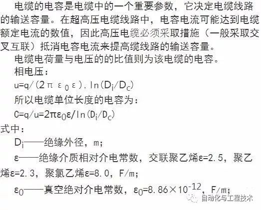
6. Capacitance of the cable
7. Calculation Example
The length of a cable type YJLW02-64/110-1X630 is 2300m, the outer diameter of the conductor is Dc=30mm, the outer diameter of the insulation is Di=65mm, the average radius of the metal jacket of the cable is rs=43.85, and the conductor resistivity is Ï20 at 20°C. = 0.017241×10⁻⁶Ω·m, temperature coefficient of core resistance α=0.00393°C-1, k1k2k3k4k5≈1, cable spacing 100mm, vacuum dielectric constant ε0=8.86×10⁻¹² F/m, dielectric constant of insulating medium ε = 2.5, the current carrying capacity is 420A during normal operation. Calculate the DC resistance of the cable, AC resistance, inductance, impedance, voltage drop, and capacitance.
Calculated as follows:
1. DC resistance
According to the DC resistance formula: 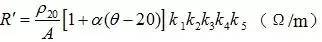
To:
R' = 0.017241 × 10⁻⁶ (1 + 0.00393 (90-20)) / (630 × 10-6)
= 0.3489×10⁻⁴ (Ω/m)
The total resistance of this cable is R = 0.3489 × 10-4 × 2300 = 0.08025 (Ω)
2. AC resistance
By the formula YS=XS4/(192+0.8XS4), XS4=(8πf/R′×10-7kS)2:
XS4=(8×3.14×50/0.3489×10-4)×10-14=12.96
YS=12.96/( 192+0.8×12.96) = 0.064
Obtained by the formula XP4=(8πf/R′×10-7kP)2:
XP4=(8×3.14×50/0.3489×10-4)×10-14=12.96
Obtained by the formula YP=XP4/(192+0.8XP4)(Dc/S)2{0.312(Dc/S)2+1.18/[XP4/(192+0.8XP4)+0.27]}:
YP=12.96/(192+0.8×12.96)(30/100){(0.312(30/100)+1.18/(12.96/(192+0.8×12.96)+0.27)}= 0.02
The formula R=R'(1+YS+YP) is:
R = 0.3489 x 10⁻⁴ (1 + 0.064 + 0.02) = 0.378 x 10⁻⁴ (Ω/m)
The AC resistance of the cable is RZ=0.378×10-4×2300 = 0.8699 (Ω)
3. Inductor
The inductance per unit length is given by the formula L = Li + 2ln(2S/Dc) × 10-7:
L1=0.5×10⁻⁷+2ln(2×100/65)×10-7=2.75×10-7(H/m)
The total inductance of the cable is L=2.75×10-7×2300=0.632×10⁻³H
4. Metal jacket inductance
The inductance of the metal sheath per unit length is given by the formula LS=2ln(S/rs)*10-7+2/3•ln2*10-7:
LS1=2ln(100/43.85)×10-7 +2/3 ▪ln2×10-7
=2.11×10⁻⁷H/m
The inductance of the cable sheath is LS=2.11×10⁻⁷H/m×2300=0.4855×10-3H
5. Reactance, impedance and voltage drop
The reactance is given by the formula X = ωL:
X=2πf×0.632×10-3=0.199Ω
The impedance is given by the formula Z=(R2+X2)1/2:
Z=( 0.86992+0.1992)1/2= 0.8924Ω
The voltage drop from the formula ΔU=IZl is:
△U=500×0.8924Ω=374.8V
6. Capacitor
The capacitance per unit length is given by the formula C=2πε0ε/ln(Di/Dc):
C1=2×3.14×8.86×10-12×2.5/Ln(65/30) = 0.179×10⁻⁶ F/m
The total capacitance of the cable is C=0.179×10-6×2300 = 0.411×10⁻³ F
Din 41612 Connector,Din 41612 Vertical Female Connectors,Din 41612 Right Angle Plug Connectors,Din41612 Vertical Plug Press-Fit Connectors
Shenzhen Hongyian Electronics Co., Ltd. , https://www.hongyiancon.com