1 Capacitor charging process
After the capacitor is turned on, under the action of the electric field force, the free electrons connected to the positive electrode of the power source of the capacitor will be transferred to the plate connected to the negative pole of the power supply through the power source, and the positive electrode is positively charged due to the loss of the negative charge. The negative electrode is negatively charged due to the negative charge, and the positive and negative plates have the same magnitude of charge and opposite signs. The charge is oriented to form a current. Due to the repulsion of the same charge, the starting current is the largest, and then gradually decreases. During the charge transfer, the charge stored in the capacitor plate increases continuously, and the voltage between the two plates of the capacitor is equal to the charge of the power supply U. Stop moving and the current is 0.
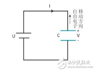
Figure 1. Capacitor Charging Process - Movement of Free Electrons Flowing Through the Power Supply
As shown in Figure 1, when a voltage value is given to U, the circuit must satisfy the Kirchhoff voltage law, so that the voltage across the capacitor is forced to jump and its value becomes U. Therefore, the circuit charging time of Figure 1 is extremely short, almost zero.
2 RC circuit as chip reset circuit
(1) RC circuit charging

Figure 2. RC circuit capacitor charging process
[1] When U = 0, the circuit has no path. There is no potential difference between the nRst point and any point.
[2] At the moment when a voltage is applied to U, electrons on the positive electrode of the capacitor pass through the point source to reach the negative plate to form a loop. At this time, the value of the power supply voltage U is distributed over the resistor R and the capacitor C. The voltage at the nRst point is equal to the voltage at the positive plate of the capacitor.
[3] With the movement of free electrons, the capacitor is charged, there is no more current, that is, there is no path in the circuit. At this point V = U, the resistance is equivalent to the wire. The potential difference between the nRst point and the negative electrode of the capacitor is U.
The charging process of the RC circuit capacitor is also short, but it is longer than the pure C circuit process. This time can be calculated by Kirchhoff's law:
R * I(t) + V(T) = U
I(t) = C * dV(t) / dt
Got
R * C dV(t) / dt + V(T) = U (1)
This is a first-order linear non-homogeneous (U ! = 0) differential equation.
First, first discuss the corresponding homogeneous equation in (1)
R * C dV(t) / dt + V(T) = 0
Separation variable
dV(t) / V(t) = - dt / RC
Integral on both sides
lnV(t) = (- 1 / RC) Sdt + lnc
Got
V(t) = e-(t/RC) + lnc
= A * e-(t/RC)
Differentiating the two sides of the equation yields:
dV(t) / dt = -(A/RC) * e-(t/RC)
Then bring the above formula into (1)
V(t) = U + A * e-(t/RC)
After copying and asking again, I finally solved this equation. When V(t) = U, it indicates that the capacitor charging process is completed. This time is related to the R*C value.
1.6 years product warranty (material and workmanship), 25 years module power output warranty
2.Industry leading plus only power tolerance: 0+3%
3.Strong framed module, passing mechanical load test of 5400Pa to withstand heavier snow load 4.17% conversion efficiency,reducing installation costs and maximizing the kwh output per unit area.
Polycrystalline Solar Panel,Poly Panel,Poly Solar Panel
Yangzhou Beyond Solar Energy Co.,Ltd. , https://www.ckbsolar.com