1 USB communication technology
USB (Universal Serial Bus) is a current universal serial bus technology. It is connected to the internal system data line of the PC through the PCI bus to realize data transmission. It has a plug-and-play function and supports hot-plugging. The length of the cable can reach about 5 m.
The USB interface signal line has 4 lines, two are the power line and the ground line (Vbus and GND), and the two are the differentially generated signal lines (D + and D-), thereby realizing the connection between the host system and the USB device For data communication, see Figure 1.
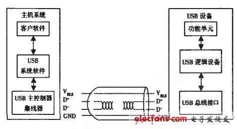
Figure 1 USB communication data flow
The USB bus 121 technology is a bus communication based on a packet exchange method. First divide the data into several blocks, then add a synchronization signal and a packet identifier before each block of data, and then add a CRC check to form a USB packet. USB bus communication uses a differential output driver to control the transmission of data signals on the USB cable, that is, by controlling the D + and D lines from the idle state to the opposite logic level, to achieve the source port packet transmission. After the packet is sent, the output drivers on D + and D- are in a high impedance state.
2 USB communication system design
2.1 Hardware design
The USB communication interface is a bridge connecting the communication between the PC and the embedded single-chip microcomputer of the automobile exhaust gas detector. Currently, a USB interface chip is used to realize the connection between the PC and the single-chip AT89C51.
Because the embedded single-chip microcomputer in the automobile exhaust gas detection system uses serial ports (TXD, RXD) to communicate in RS232 mode, the connection mode between the USB chip and the single-chip AT89C51 must also be RS232 serial communication mode. Therefore, this article adopts the conversion chip PL-2303HX which PROLIFIC company can realize the USB interface to RS232 serial port. According to the design requirements of the automobile exhaust gas detector USB communication system, the USB communication interface circuit design is shown in Figure 2.
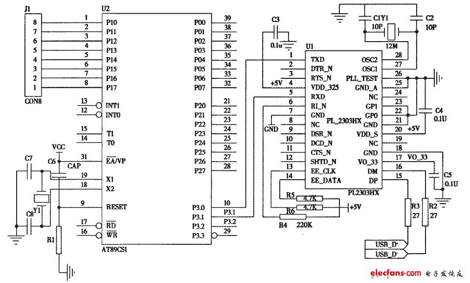
Figure 2 USB communication interface
The connection between the USB plug and the USB chip is realized through the four endpoints USB-D +, USB-D 1, GND and VO 3.3. Since the USB chip PL2303HX supports a RS232-like interface, it contains full-duplex transmission and reception (RXD, TXD) Serial port, so the PL2303HX chip and the RS232 serial port of the single-chip AT89C51 can be directly connected with three wires RXD, TXD, GND, that is, the RXD, TXD and GND of the USB chip PL2303HX are connected to the TXD, RXD and GND of the single-chip AT89C51, both sides Can send and receive.
2.2 Software design
2.2.1 Communication method
In this paper, the USB communication system adopts asynchronous half-duplex communication, that is, one party of communication sends and receives alternately. The data format of communication is 10 bits per frame, including 1 start bit, 8 data bits and 1 stop bit, as shown in Figure 3.
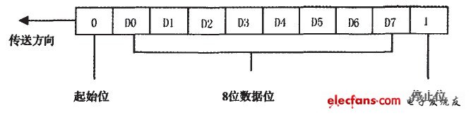
Figure 3 byte transmission sequence
Here set the serial port of the single-chip microcomputer to use T as mode l, which is 10-bit asynchronous communication, and the on-chip timer Tl as the baud rate generator, the baud rate is 2400bps; SMI, set to 0 and 1, respectively, to set its serial port to mode l; when C / T = 0 and M1M0 = 10 in the timer / counter Tl control register TMOD, AT89C51 timer / counter Tl is in timer mode , Set to mode 2. As a baud rate generator, its baud rate is expressed as:
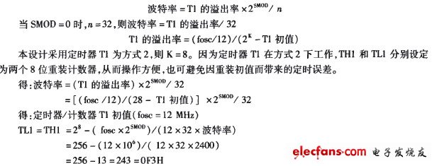
Then: The initial value of the timer Tl should be set to 11Ll = THI = F3H, and the timer Tl interrupt should be disabled to avoid unnecessary interruption due to the overflow of the timer T1.
2.2.2 Communication protocol
Before communicating, both parties must first formulate a specific communication protocol according to the functional requirements of the system, and then write the corresponding communication program. Communication protocol in this article:
â‘ Both communication parties use 2 400 bps to transmit data. Both the PC and AT89C51 work in serial port mode (1 start bit, 8 data bits, 1 stop bit).
â‘¡AT89C51 adopts serial port interrupt mode when sending and receiving data.
â‘¢ The PC sends out the data collection command (handshake signal). After receiving the handshake signal from the serial port of the single-chip AT89C51, the test data stored in the memory of the AT89C51 is sent to the PC through the USB communication interface, and the data collection is completed.
Home and indoor or building air filters remove unwanted particles like dust, pollen, pet dander and mold and ensure even the most allergy prone can breathe easily year–round. However, choosing the right filter for your home can be a rather involved process. To help, here are the most common indoor air filters and what each of them provides. The filters are the simplest basic component for air filtration solution through your heating and cooling system ,It is important that you constantly monitor the buildup of debris on these filters as well because it can easily be recycled into the air supply. It is easy change and maintain.
Indoor Air Purification Filter & Air purifier filter
AC Filter,Air Conditioner Filter,AC Furnace Filter,Home AC Filter
Donguan Bronco Filter Co., Ltd , https://www.broncofilter-cn.com