This paper first introduces the implementation principle of various frequency dividers, and gives the simulation results through the combination of VHDL text input and schematic input on the FPGA development platform. Finally, through the analysis of various frequency divisions, using the hierarchical design idea, a general-purpose numerical control frequency divider based on FPGA is designed and integrated, and the frequency division of different multiples and duty ratio can be realized by adjusting the controllable port. Device.
1 Introduction
The frequency divider is one of the most important modules in digital systems and is widely used in various control circuits. In practice, designers often need to pass a standard frequency source through a crossover technique to meet different needs. Common crossover forms are: even frequency division, odd frequency division, half integer division, fractional division, and fractional division. In some strict cases, there is also a duty cycle requirement. The even-numbered dividers and odd-number dividers with non-equal duty ratios are easier to implement, but it is more difficult to implement for a half-integer divider and an odd-number divider with a 50% duty cycle.
This paper first introduces the implementation principle of various frequency dividers, and simulates it with VHDL hardware description language. Finally, a design method of controllable universal frequency divider is proposed. This method can realize arbitrary frequency division and low resource consumption. With programmable advantages.
2. Even frequency divider
The even-numbered divider is relatively simple, that is, the counter is used to count and flip the original clock signal that needs to be divided.
For example, it is necessary to divide M=2N (N is a natural number). When the count value is 0~k-1, it outputs a high level. When the count value is k-1~2N-1, it outputs a low level and counts at the same time. The value is reset. This cycle can achieve even division of any duty cycle, where M and k are preset numbers, which can be set according to the division ratio and duty cycle requirements. As shown in Fig. 1, when k = N, an even division with a duty ratio of 50% can be achieved.

Figure 1 Four-way simulation results with a 50% duty cycle
3. Odd crossover
The implementation of an odd divider with any duty cycle is similar to the even divider. However, any odd-numbered frequency division with a duty ratio of 50% cannot be implemented by the same method as described above.
The following describes a common implementation method.
Implementation principle: Two different edge flip-flops (one on the rising edge and one on the falling edge) are implemented, the details of which are the time difference of 1/2 original clock cycles.
As shown in FIG. 2, when M=2N+1 is divided, k1 is a signal at the rising edge of clk and the counting period is M. When the counter value is 0~N, k1 remains low, and when the count value is N+1~2N, k1 remains high.
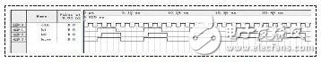
Figure 2 5-way simulation results with a 50% duty cycle
K2 is the same as k1, the only difference is that k2 is changing on the falling edge of clk. Finally, k2 and k1 are ORed to obtain any odd frequency divider with a duty cycle of 50%.
4. Half integer crossover
The principle of a semi-integer divider is shown in Figure 3 [3]. It mainly includes three parts: modulo M counter, XOR module and 2-way module. The design idea is: through the XOR gate and the divide-by-2 module to form a pulse adding circuit that changes the input frequency, that is, M counting pulses are generated in M-0.5 input signal periods, and the period of one of the counting pulses is changed. It is a period containing two pulses. The specific implementation of this change is to XOR the original clock signal with the output of the divide-by-2 module.
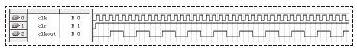
Figure 3 Semi-integer divider principle
In addition, it is not difficult to find that this schematic can also achieve an odd-numbered division of 2M-1 times the duty ratio of 50%. When M=3, the simulation results are shown in Fig. 4. The output port q of the schematic diagram is divided by 5 with a duty ratio of 50%, and the output port C is divided by 2.5.
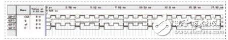
Figure 4 Semi-integer divider simulation results
5. Implementation of CNC universal frequency divider
In summary, a universal frequency divider with adjustable duty cycle can be realized by using a modulo N counter, a pulse adding circuit, and a control module. A hierarchical design approach can be used in the specific design process. First, design the circuit components of each component in the general-purpose frequency divider, and then call each component through the method of component instantiation to realize the universal frequency divider.
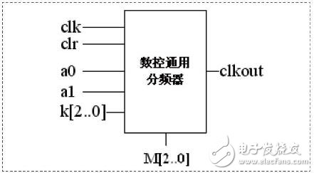
Figure 5 Schematic diagram of the universal divider
among them:
The implementation of the modulo N counter can be done in two ways:
The first is to call the parameterized counter module LPM_COUNTER in the LPM library, according to the wizard to set the parameters, QuartusII will generate the corresponding. Vdh counts the text. In order to be able to call the count text, we finally need to design an instantiation program for the count text in the VHDL language and set it as the top-level file. The second is to use the VHDL description language to achieve.
The binary module is implemented by using a D flip-flop, that is, the output signal Q of the D flip-flop is fed back as an input signal, and the highest bit of the output signal of the modulo N counter is used as the clock signal of the D flip-flop.
The top schematic is shown in Figure 5. Where a is the frequency division mode selection, when a=00, the even frequency division is performed; when a=01, the duty ratio is not 50% odd frequency division; when a=10, the odd frequency division with the duty ratio of 50% is performed. Screen; semi-integer division [2] when a=11. The role of port M is to control the number of divisions. The role of port K is to adjust the duty cycle when even (M=2N) and odd (M=2N+1) are divided. When k=N, the duty ratio is 50%.
6 Conclusion
The ultimate goal of this design is to realize the versatility and practicability of the frequency divider. In this design, the bit widths of the control ports M, K, and the counter N are all based on the parametric design idea, and the user can modify it according to the needs. Different crossover requirements have achieved versatility to a certain extent.
LED Tunnel Light is a special lamp used in tunnel lighting to solve the "black hole effect" or "white hole effect" ,which caused by the sudden change of vehicle brightness when entering or leaving the tunnel.
Through the softening treatment,LED tunnel light will not make the person produce dazzling or other uncomfortable reaction.
LED Tunnel Light
Waterproof tunnel light,Waterproof LED 150W tunnel light,Portable IP66 mining tunnel light,IP66 explosion-proof mining tunnel light
Jilin Province Wanhe light Co.,Ltd , https://www.wanhelight.com